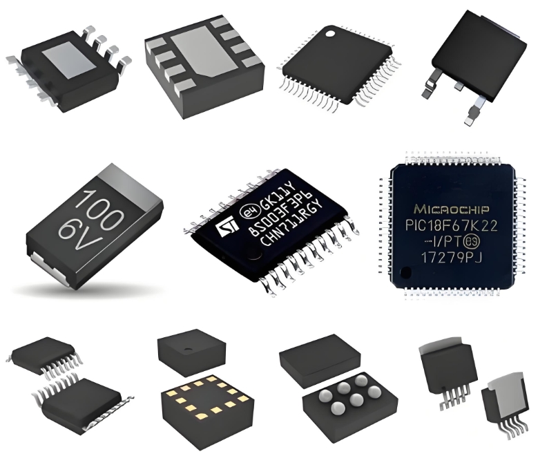
**ADM241LJRS: A Comprehensive Technical Overview and Application Guide**
The ADM241LJRS is a robust, high-speed, **low-power RS-232 transceiver** from Analog Devices, designed to meet the EIA/TIA-232E and V.28/V.24 specifications. Housed in a compact 16-lead SOIC package, this integrated circuit is engineered for **reliable data communication** in electrically noisy environments, making it a cornerstone component in industrial control, telecommunications, and embedded computing applications.
At its core, the ADM241LJRS features a single driver and a single receiver. A key technical advantage is its **on-board charge-pump circuitry**, which requires only a single +3.3V or +5V power supply to generate the necessary ±5.5V RS-232 voltage levels. This eliminates the need for expensive dual power supplies, simplifying system design and reducing both board space and overall cost. The device is capable of sustaining **data rates up to 115kbps**, ensuring compatibility with a wide range of standard baud rates for serial communication.
The **enhanced ESD protection** of the ADM241LJRS sets it apart from many competitors. All transmitter outputs and receiver inputs are protected to ±15kV using the Human Body Model (HBM). This formidable level of protection safeguards the device and the more sensitive circuitry behind it from electrostatic discharges encountered during handling or operation, drastically improving field reliability and reducing system failures.
**Application Guide and Circuit Implementation**
Implementing the ADM241LJRS is straightforward. The primary application is to convert logic-level signals from a UART (Universal Asynchronous Receiver/Transmitter) within a microcontroller or microprocessor into RS-232 compliant signals for transmission over longer cables, and vice-versa for reception.
A typical connection diagram involves:
1. Power: Decouple the **VCC pin (typically +3.3V or +5V)** to ground using a 0.1µF capacitor placed close to the package.
2. Charge-Pump Capacitors: Connect four 0.1µF capacitors to pins C1+, C1-, C2+, and C2- as specified in the datasheet. These are critical for the internal voltage doubler and inverter to function correctly.

3. Interface: The driver input (DIN) is connected to the UART's transmit (TXD) pin. The receiver output (ROUT) is connected to the UART's receive (RXD) pin.
4. Shutdown Control: The **SHDN (Shutdown) pin** allows for placing the device in a low-power standby mode, reducing the supply current to a mere 5µA. Pulling this pin low activates this feature, which is crucial for battery-powered applications.
When designing the PCB, it is essential to place the charge-pump capacitors as close as possible to the IC to minimize parasitic inductance and ensure efficient operation. Furthermore, the use of a ground plane is highly recommended to maintain signal integrity.
ICGOOODFIND: The ADM241LJRS is an **exceptional solution for modern serial port design**, offering an optimal blend of integration, robust ESD protection, and power efficiency. Its ability to operate from a single supply while delivering full RS-232 voltage compliance makes it an indispensable component for designers seeking to add a durable and reliable serial interface to their systems.
**Keywords:**
1. **RS-232 Transceiver**
2. **ESD Protection**
3. **Charge-Pump Circuitry**
4. **Low-Power Operation**
5. **Data Communication**
